
Pump Impeller Repair
Contributed by: RepairEngineering

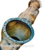
This is a model of a worn-out impeller from a pump used in a mining application.
In this project, the worn impeller wear rings and drive hub surfaces (indicated by the arrows) were restored to as-new condition.
Project Overview

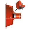
This is a partial cut-away view of the impeller. Notice the worn surfaces indicated by the arrows.
Impeller Wear Ring Repair Set-up

The original wear ring surfaces were machined undersized to clean-up the worn material and to allow for the installation of new replaceable wear rings.
Impeller Drive Hub Bore Repair Set-up

The impeller drive hub bore was machined to an oversized diameter and counterbored as shown in this view.
Also, as shown in this view, the oversized bore was threaded to allow for the installation of a custom repair insert.
Manufacturing New Custom Wear Rings

New custom replaceable wear rings were created in this step.
The wear ring design allowed for excess material on the outer diameter and length.
(Once the wear rings were installed on the impeller, the excess material was machined to the desired outer diameter and length.)
The inside diameter of the new wear rings was designed to allow for a shink fit, once installed. A shrink fit design of .001" per inch of diameter is a good rule-of-thumb for general-purpose repair applications such as this.
Manufacturing New Impeller Drive Hub Insert

A custom thread insert was created to repair the impeller drive hub.
Notice that the head of the insert was designed with a larger (unthreaded) diameter to allow for engagement in the counterbore that was created in an earlier step.
As was the case with the wear rings, the thread insert was designed with excess length that was machined-off once installed in the impeller.
Installation of New Components

In this step, the impeller repair parts that were created earlier were installed.
To install the insert, threadlocker compound was applied to the threads and then threaded into the impeller drive hub until the head of the insert seated against the face of the counterbore.
To install the new wear rings, they were heated to allow them to expand. The required temperature differential was calculated using the coefficient of thermal expansion data for the bronze wear ring material.
Once expanded, the heated wear rings slipped easily onto the prepared surfaces of the impeller. After the rings cooled, the interference fit held them securely in position.
Machining New Components to Final Dimensions

After the wear rings and drive hub insert were installed on the impeller, the excess material was removed by machining the surfaces to their final dimensions.
As shown in this view, the drive hub insert was faced, bored, and a keyway was broached. In addition, the insert was staked to the impeller to help secure it in position.
Cross-Section View of Completed Impeller Repair:

This is a cross-section view of the completed repair showing the installed wear rings and drive hub.
Completed Repair:

This is a photo of the actual completed impeller repair project.

Copyright © RepairEngineering.com. All rights reserved.
Content and images may not be reproduced in any way without permission.